
Figure 1. The Microcontroller based Valentines Card.
Pretty much, most of the details are on their site. The project requires the USB Nerd Kit, wire strippers (I use a set of auto-strippers that I bought several years ago, when you have to strip wires a lot and quickly they are great to have, and it’s a pain to use the old fashion kind), and some basic construction tools. I used a piece of foam/cardboard I picked up from Walmart to build the heart, a Exacto knife to cut the hole for the LED Faceplate, and a drill to drill holes for the LED’s. To hold everything together, I used Gorilla Glue, which had a fortunate side effect of causing the Styrofoam in the board to bubble up before hardening, which worked great to hold all the circuit pieces onto the poster board.
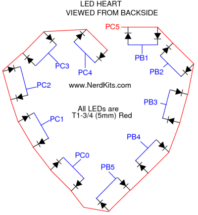
Putting the circuit together was simple. I first followed the directions in the Nerdkit PDF file to build the base circuit (in the Nerdkit PDF, this is all the way up to step 10, which includes building the circuit, attaching the LCD screen, and attaching the programmer, and compiling and installing some test programs). From there, the rest of the project involved wiring up the LED’s as indicated in this template:
A little hint, to do the wiring from LED to LED, I used an old fasion wire wrap tool. This took maybe 15-20 minutes to completely wire the entire common wire run across the back of the template. To do the individual connections, I again, used a wire wrap tool to connect two posts in the LED’s, then I would only need to connect a single wire from the MCU to the pair.

Figure 2. Wire Wrap. Notice the single large white wire connecting to the post at the bottom of the image. Much easier than taking two wires from each post and trying to connect them in the middle. A single wire wrap takes like 5 seconds to complete.
Because this was going into a permanent card, I ended up soldering everything onto a circuit board. I ended up using a simple 6” circuit board from Radio Shack. The reason I chose this board is because it had the two side rails for both +5V coming from the voltage regular and a ground, had a 7mm center divide for the MCU, and to has a layout similar to the breadboard included in the Nerdkits kit, with numbered sides, so I could follow the instructions exactly. I also connected two 16 pin IC sockets back to back in place of the MCU during construction, this way I could solder everything to the board without the microcontroller in place and I wouldn’t have to worry about damaging the chip due to heat from the soldering iron. I could plug in the chip when I was done with construction.
The only modification I made to the circuit was to solder an additional four wires to act as “Posts” for the MCU programmer. I put 1 wire on the +5V rail, 1 on the ground, and 1 wire on each of the appropriate pins for the programmer to work. Then, if I needed or wanted to change anything, I would only need to flip the switch to set the chip into programming mode and attach the USB programmer to the posts using alligator clips (if I had time, I would have used some sort of connectors).
So how did it work? Initially, I ran into some issues. The code provided would cause the MCU to lock up unless I changed the delay timing. Thanks to the excellent support from Nerdkits, I was able to determine this was not a problem with the code, but with the version of AVR (the programming environment) for Windows that I was using. Once I updated to the newest version of AVR, everything worked perfectly.
So how would I rate my experience working with the Nerdkits tools. I am actually very impressed. There are a lot of Microcontroller kits out there (Basic Stamp, Adafruit). I got the USB Nerdkit for 80 dollars. A Basic Stamp kit runs about the same price at Radio Shack, the Adafruit kit run from anywhere from 30 bucks on up, depending on what you need (the equivalent to what I got from Nerdkits is about 65 bucks, minus the LCD screen and guide). So what attracted me to Nerdkits (besides the Slashdot advertisement), and what will keep me going back to them? Most importantly, the excellent support. I sent their support a message around midnight on Saturday. I had a response waiting in my Inbox on Sunday morning when I woke up. I can’t get that kind of support from most big vendors, including ones that I've spent thousands of dollars on server equipment and have "Gold" support with, so to get that from a small shop is incredible. Not only that, I had a follow up message a few hours later with the fix. In the message the guy said he played around with it and figured it out. This wasn't some dope in a call center reading from a script, but an actual guy (according to their site, an MIT engineer) who took the time to replicate and troubleshoot the issue, and on a Sunday. I can’t get that kind of support from people I know personally. I liked the included tools. The IDE used to program is an open source one, so I can play around with it, and maybe try to port the compiler over to something like Eclipse if I want to. The instructional material was easy to follow, and their are tutorial videos on their site. I had my initial kit up and running in less than 2 hours by following their instructions. The example kits are fun, and I like the fact that I can write code in C for the microcontroller. While I know BASIC and could have managed on a BASIC Stamp, I prefer C, especially for doing things like bit-shifting and working with registers on the microcontroller. And the end result is a lot simpler than the BASIC stamp modules bulky modules.
I’ve been wanting to build a few mini-moving lights for a Halloween project, and most of the components are already built in examples on their site (a combination of their Servo-Water gun (using 2 axis instead of 1) and some PWM ultra-bright Red, Blue, and Green LED’s will work for what I want). Overall, I am very impressed and happy with my experience from these guys.
And most importantly, the wife loved it :)

Figure 3. This looks a lot more complicated than it really is. I used ribbon style wire to go to each LED pair, and all green wires to connect to the LCD (hence the bundle of green wires). I lost the batter clip I bought, so I ended up using Duct Tape to hold the battery in place.

